
Grip planning
C Stand With Boom Arm: Plan the Position Backward
Turn one required accessory position into a practical equipment worksheet by tracing the boom, grip head, riser, base, and every connection in reverse.
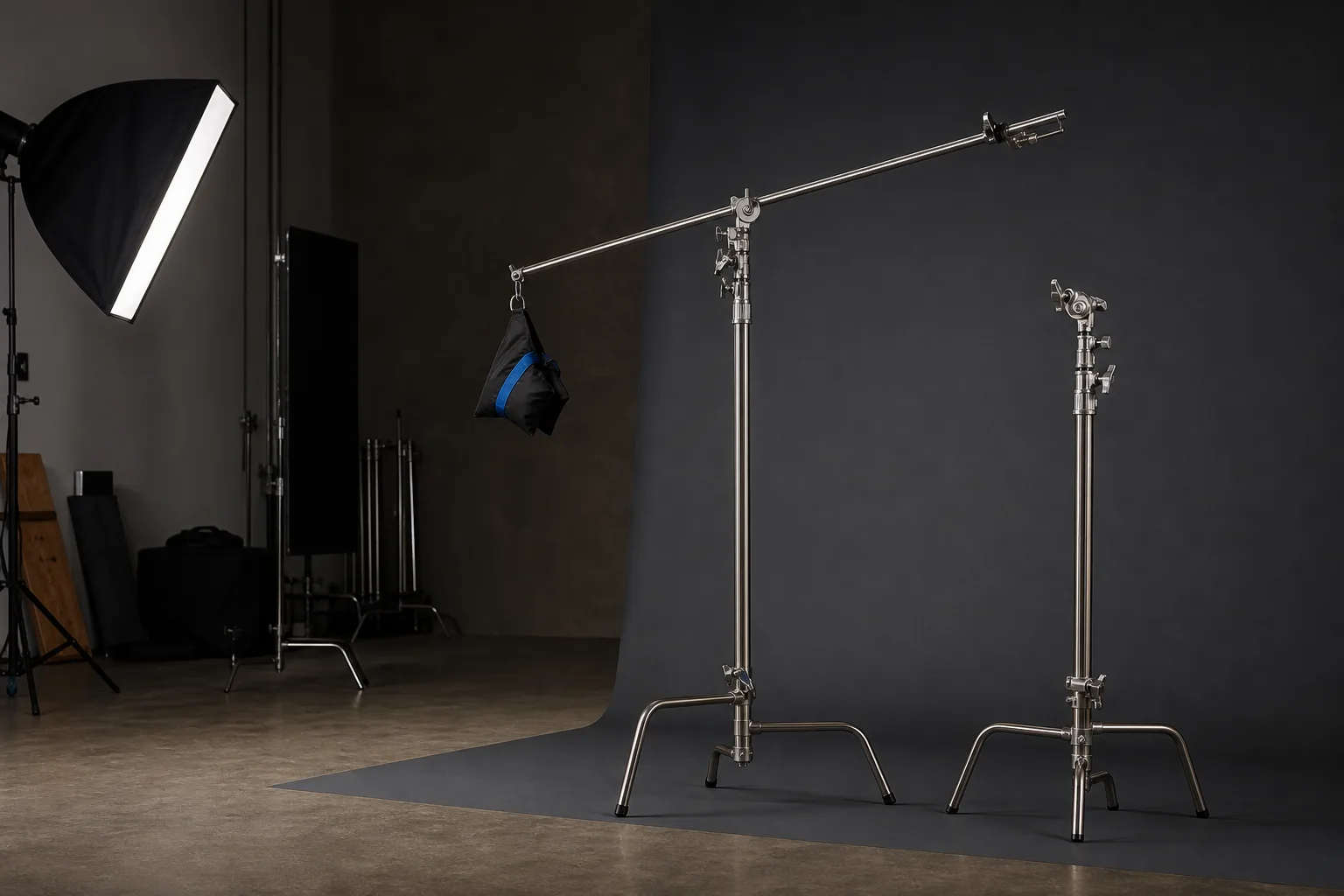
Shopping for a C stand with boom arm often begins with the largest height or arm number in a listing. That is useful catalog information, but it does not answer the first planning question: where must the actual accessory sit for the shot? Start at that required working point, then trace the support path backward through the arm, grip head, riser, base, and floor area.
This method is narrower than a general C-stand size guide. It turns one real camera setup into a worksheet for comparing configurations. A C stand with boom arm remains a system of separate components and connections; reach at one point does not establish capacity, compatibility, or permission to use a particular accessory.
Manufacturer pages illustrate why the component chain matters. Tiffen documents a named Lowel grip head and package components; Matthews presents its 20-inch C+Stand as a particular riser, turtle-base, grip-head, and arm combination. Those facts do not describe every similarly named kit. Verify the exact equipment and current instructions before use.
Start with the required working point
Mark the center of the accessory where it must be during the final take. This is the endpoint of the plan, not the place to begin guessing stand dimensions. Record it relative to stable references: the floor, subject mark, product table, background, and camera frame.
Your worksheet should answer:
- What accessory or attachment point is being positioned?
- What is its required height above the supporting surface?
- How far sideways must it sit from a possible riser location?
- Which edge of the camera frame must the support stay beyond?
- Does the point change between seated, standing, wide, and close shots?
- What nearby door, chair, table, cable route, or ceiling feature limits movement?
Use the attachment point rather than the center of a light or modifier when checking dimensions. An adapter or clamp can move the connection away from the visual center. Sketch the complete accessory outline too: its connection can be outside the frame while the accessory remains visible.
For recurring shots, make a separate row for each working point rather than averaging them into one “normal height.” A C stand with boom arm needs a usable path to each point, and the route may reveal an obstruction that the endpoints do not.
Map vertical height and lateral offset separately
Draw a simple side elevation through the accessory and proposed riser. Mark the working-point height first. Then draw a separate horizontal line from that point toward the riser. These are two different requirements:
- Vertical height is the distance from the supporting surface to the connection at the working point.
- Lateral offset is the sideways distance from the riser axis to that connection.
Keeping them separate prevents a common shopping mistake: treating the published boom dimension as if the whole length becomes usable sideways reach. Part of a C stand boom arm can remain on the other side of the grip head, while the head, end hardware, adapter, and accessory each occupy space. Angle also changes the relationship between vertical and lateral position.
Record dimensions as requirements, not promises. Write “required lateral offset,” not “arm reaches,” until the exact head position, connection, arm path, and instructions have been checked.
Account for the arm path and adjustment envelope
The desired endpoint is only one point in a larger operating envelope. Draw the C stand arm from the working point back through the proposed grip-head joint, then sketch the space it could occupy while moving from the low rehearsal position to the planned position. Include the accessory outline at both ends of the move.
Check that envelope against:
- the top and sides of the camera frame;
- the subject’s real movement, not only the starting mark;
- shelves, ceiling fixtures, doors, backdrop supports, and furniture;
- another stand, light, flag, or monitor already assigned to the set;
- the cable route and the service loop required by the exact powered equipment;
- the parked or lowered position used for changes.
A diagram makes this backward chain easier to inspect. Compare its working point, arm path, riser, frame boundary, footprint, and protected equipment zone with your own room drawing.
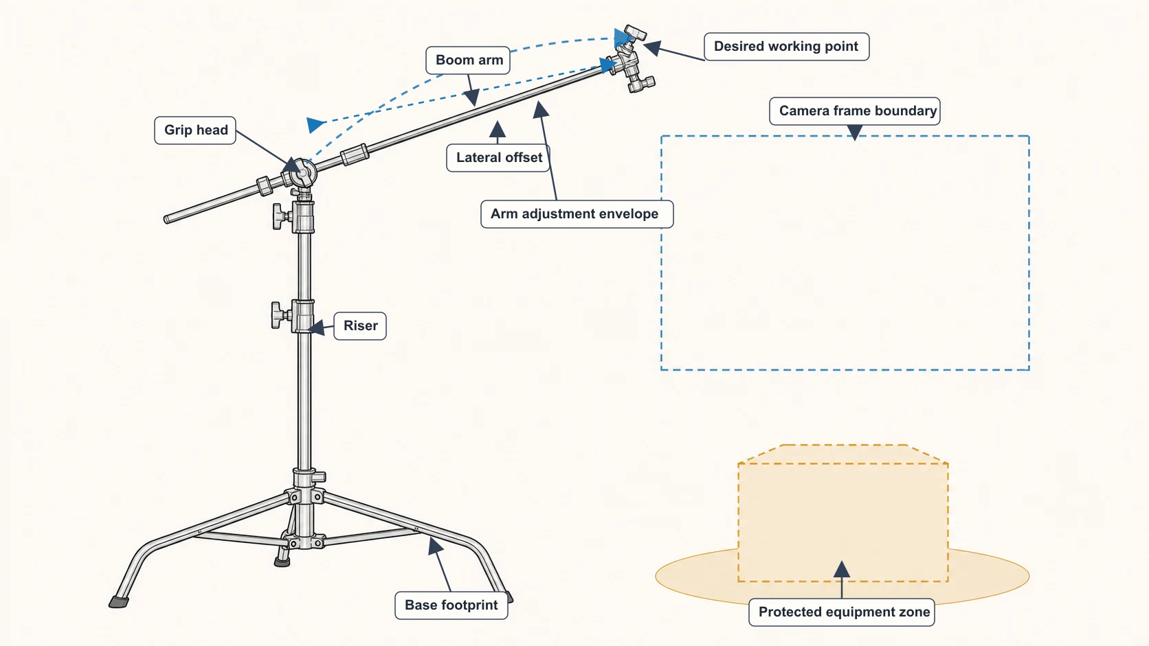
A clear final position does not guarantee a clear adjustment. A C stand with boom arm can remain outside a locked frame yet cross the frame, furniture, or a person’s route while being lowered. If the envelope cannot remain in a controlled equipment area, revise the layout before comparing kits.
Locate the riser and base outside the frame
Project the arm path backward until it meets a plausible grip-head and riser location. Now switch to a floor plan. Draw the riser axis, then the complete base footprint for the exact configuration under consideration. A dot for the center column is not enough.
Keep three boundaries visible:
- Camera frame boundary: the floor projection of the widest composition you intend to record.
- Base footprint: the complete area occupied when the documented base is opened as required.
- Protected equipment zone: the footprint, arm envelope, accessory movement, and controlled cable area together.
Do not hide the base by placing it millimeters beyond the image edge. Leave tolerance for a small camera move, stabilization crop, or wider take. Look from the subject’s entrance too; a chair or table may conceal equipment that is obvious from behind the camera.
This step distinguishes reverse planning from shopping by maximum reach. Moving the riser closer can reduce the required offset but may put the base in frame. Moving it farther away can clear the base while increasing the offset and adjustment envelope. The worksheet exposes that tradeoff before a product title is allowed to settle it.
Verify every connection on the exact equipment
Trace the support chain one interface at a time:
accessory → accessory adapter or clamp → arm-end connection → boom arm → grip head → riser → base
Write the documented connection at every arrow. Do not fill a gap with “standard,” “universal,” or “looks compatible.” Tiffen’s Lowel page, for example, identifies 5/8-inch and 3/8-inch openings for its named grip head and describes specific package components. That information is useful when reading that product’s documentation; it is not a blanket rule for another head, mirrored arrangement, adapter, or marketplace kit.
The same caution applies to a C stand with boom arm sold as a set. “Includes arm” does not confirm the accessory connection or an approved working configuration. Record model identifiers, package contents, instructions, and unresolved interfaces. An unresolved arrow means the comparison is not finished.
Compare catalog configurations without inferring capacity
The LOMTAP C-Stands and Boom Arms collection and comparison page can turn the worksheet into a shortlist. Use the published listing title and available catalog fields only for the questions they actually answer.
| Catalog configuration | Published boom wording to verify | Useful worksheet question |
|---|---|---|
| 6.8 ft C-stand kit | Listing title names a 2.8 ft / 87 cm boom arm | Does the planned offset and connection chain fit this exact configuration? |
| 10.8 ft C-stand kit | Listing title names a 4.2 ft / 128 cm boom arm | Does the room need this listed geometry, and can every interface be confirmed? |
| 10.5 ft C-stand kit | Listing title names a 4.2 ft / 128 cm boom arm | Which current package details differ from the other listed configuration? |
The words heavy duty C stand with boom arm appear in marketplace-style product naming. Treat “heavy duty” only as listing language. It is not an article-backed load rating, safety conclusion, or reason to skip the exact Amazon listing and supplied documentation. LOMTAP catalog entries without a dated source snapshot intentionally do not present price, rating, or availability as verified facts.
Compare only currently published dimensions and package details, then confirm setup-critical facts with exact seller documentation and the material supplied. If fields conflict or a connection is missing, keep it unresolved.
Run a low-position rehearsal before the shoot
After choosing documented components, rehearse at an accessible low position without relying on a valuable accessory to prove the plan. Follow the exact manuals. Test the worksheet’s geometry and workflow; do not improvise a load test.
- Mark the camera frame, working point, proposed riser axis, and protected equipment zone.
- Place or outline the documented base footprint at the proposed location.
- Identify each component and connection in the chain.
- Rehearse the arm path from the low position toward the required direction while the area is clear.
- Check the frame, furniture, subject route, operator route, and cable plan again.
- Stop if a connection, instruction, dimension, or adjustment behaves differently from the worksheet.
- Complete the separate C-stand setup checklist before the real shoot.
Repeat the rehearsal whenever the accessory, adapter, arm position, riser location, camera frame, or room layout changes. A previous rehearsal applies only to the configuration that was actually checked.
Use the backward plan as the purchase checklist
The useful output is not a claim that one kit has “maximum reach.” It is a chain of requirements: desired working point, separate vertical height and lateral offset, clear arm envelope, plausible grip-head and riser location, complete base footprint, verified interfaces, and a controlled floor area.
Use that chain to compare each C stand with boom arm rather than shopping from one headline number. Compare LOMTAP kit configurations and their published boom dimensions, then confirm current documentation and connection details for the intended setup. If any link in the chain remains unknown, keep it on the worksheet instead of converting it into a compatibility or capacity assumption.
Related equipment
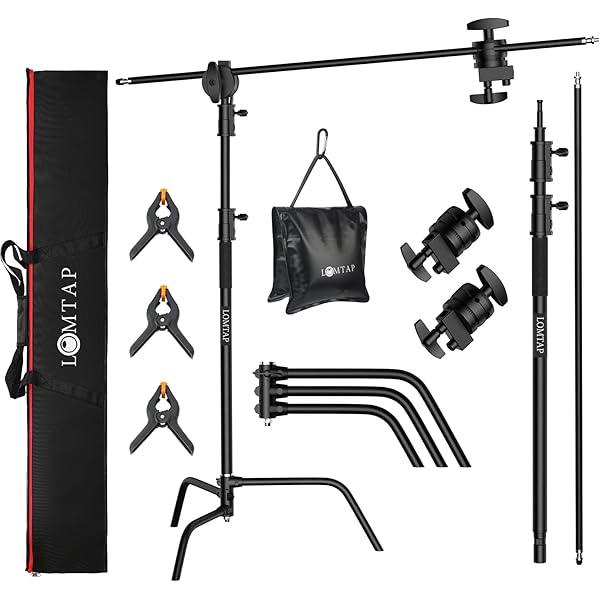
LOMTAP · C-Stands & Boom Arms
10.8 ft Heavy-Duty C-Stand KitBlack · 330 cm stand · 128 cm boom
See current price on Amazon.
Check on Amazon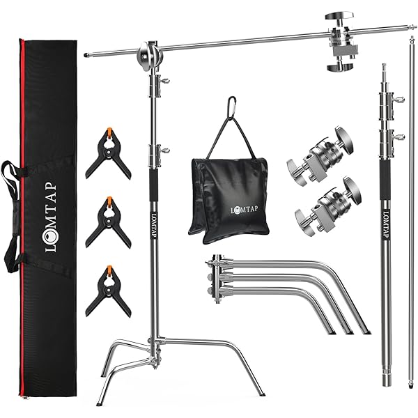
LOMTAP · C-Stands & Boom Arms
6.8 ft Stainless C-Stand KitSilver · 210 cm stand · 87 cm boom
See current price on Amazon.
Check on Amazon
LOMTAP · C-Stands & Boom Arms
10.5 ft Heavy-Duty C-Stand KitSilver · 330 cm stand · 128 cm boom
See current price on Amazon.
Check on AmazonContinue reading
Back to all guidesGrip fundamentals
C-Stand Size Guide: Choose for the Set, Not the Number
A useful C-stand size decision starts with the shot, the room, and the accessory position. This guide turns those constraints into a repeatable shortlist.
Studio workflow
C-Stand Setup Checklist for a Cleaner, Safer Set
A repeatable C-stand setup is a sequence, not a last-minute tightening pass. Work through the room, stand, accessory, and cable checks in order.
Grip fundamentals
C-Stand vs. Light Stand: Choose by the Job
C-stands and light stands overlap, but they organize a set differently. Compare the job, connection, room, and moving pattern before choosing either format.